Interfacing Carbon Monoxide(CO) Sensor(SPEC Gas Sensors) with Arduino
Published by Ram Singh on 24th Jun 2019
Make your own CO gas detector
Required Materials
- Arduino Uno - 1
- Breadboard - 1
- Jumper wires
- Resistors 10 kΩ - 2
- Resistor 100 kΩ - 1
- SPEC CO Gas Sensor - 1 (https://www.evelta.com/sensors/gas-sensor/110-102)
Connection
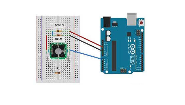
Connection Diagram of Carbon Monoxide(CO) Sensor with Arduino
1- Cut the two pins that are not labeled, then center the sensor on the breadboard.2- Use a short jumper to short the R and C pins (counter and reference). Use another short jumper to short the W1 and W2 pins (this is just giving an extra route for the current as the pins are already shorted on the PCB).3- Connect the R/C pins of the sensor to A0 of the Arduino board
4- Connect W1/W2 pins to GND via 10 kΩ resistor
5- Connect W1/W2 pins to 3.3V via 100 kΩ resistor6- Finally use a 10 kΩ resistor (R1) to connect the R/C pins to the W1/W2 pins.
Code
#include "Arduino.h"
#include "ULP.h"
// These constants won't change. They're used to give names to the pins used and to the sensitivity factors of the sensors:
const int C1 = A0;
const int T1 = A3;
const float Sf1 = 4.05; //nA/ppm replace this value with your own sensitivity
float temp1;
float TZero;
float Vzero1;
CO sensor1(C1, T1, Sf1);//Sensor Types are EtOH, H2S, CO, IAQ, SO2, NO2, RESP, O3, and SPEC (custom)
//O3 sensor2(C2, T2, Sf2);//Example O3
//H2S sensor3(C3, T3, Sf3);//Example H2S
// Include these if using different boards with different voltages
//float ULP::_Vcc = 5.0; //analogRead Reference Voltage
//float ULP::_Vsup =3.3; //voltage supplied to V+ of ULP, ideally 3.3 Volts
void setup() {
Serial.flush();
Serial.begin(9600); // initialize serial communications at 9600 bps:
Serial.println();
Serial.println("Setting Up");
Serial.print("Vsup for all sensors = ");
Serial.println(ULP::_Vsup);
Serial.print("Vcc for all sensors = ");
Serial.println(ULP::_Vcc);
Serial.print("Vref for sensor 1 = ");
Serial.println(sensor1._Vref);
// Using resistor values from board R1, R2, R3 are for setting _Vref and Bias, while R6 sets the gain
// If using modified or custom boards set Vref and Gain like this
//long int R1 = 61900, R2 = 1000, R3 = 1000000;
//int bias = 1; //alternatively bias=-1; for negative bias.
//sensor1.setVref(R1, R2, R3, bias); //will set the new Vref for custom sensor voltage ladder. bias is necessary to set the correct arrangement
//sensor1._Gain = 49900; //resistor R6
// Vref is not necessary if zero() is called for each sensor. If you already know the sensor zero you can comment this out, and set the zero with zero1 = measured mV.
Serial.print("Vzero = ");
Serial.println(Vzero1 = sensor1.zero()); //.zero() sets and returns the baseline voltage at current temperature with only clean air present
Serial.print("Tzero = ");
Serial.println(sensor1._Tz);
//sensor1.setXSpan(); //Must have previously zeroed in clean air, returns new span factor.
//When calibrating the temperature use "LOW"/"HIGH" for the temperature range ie .setTSpan(40.2, "HIGH") where T is the current high temperature
//sensor1.setTSpan((71 - 32.0) * 5.0 / 9.0, "LOW");
Serial.println("Finished Setting Up");
Serial.println("T1, mV1, C1");
}
void loop() {
temp1 = sensor1.getTemp(1,"F"); // Use .getTemp(n, "F") to get temp in Fahrenheit, with n as int number of seconds for averaging and "F" or "C" for temp units
Serial.print(temp1);
Serial.print(", ");
//Use .getVgas(int n) where n is the number of seconds to average
//Use ._Vref to read the reference voltage (voltage offset)
Serial.print(sensor1.getVgas(1));
//Use .getConc(1, temp1) where temp1 is in deg C for temperature corrected span
Serial.print(", ");
Serial.println(sensor1.getConc(1,sensor1.getTemp(1)));
delay(100);
}
See the result in Serial Monitor.