Single Pin LCD Communication
Published by Fayaz Hassan on 23rd Jun 2019
LCD is the most common output device to microcontroller (MCU) projects. The LCD module can be connected to MCU using 8 bit or 4 bit parallel interface which requires minimum 10 pins or 6 pins of MCU for communication, if R/W pin of LCD is permanently used as write. So many pins of MCU availability and connection wiring makes the project complex.
The serial communication can reduce the number of pins required to communicate LCD to 3. i.e., serial data , clock and enable pins using shift register IC. The circuit explained here can communicate with LCD using only one pin of MCU.
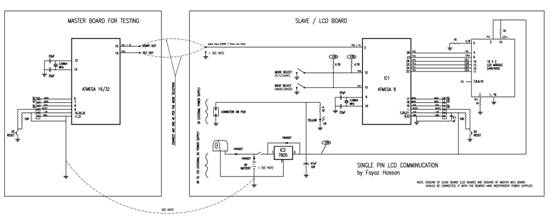
IC1, ATmega8 is cheaper, yet powerful AVR microcontroller working as heart of the circuit, which communicates with the Master/Host MCU (may be AVR or PIC or any other MCU) and process the data to LCD module. The IC1 is programmed for two modes, i.e., USART mode and PLT (Pulse Low Time) mode. Once, USART mode is selected, it can communicate at 9600 (commonly used) or 38400 (high speed) baud rate. The higher baud rate is to be supported by Master/Host MCU. The mode and baud rate can be selected by miniature switches or jumpers. The main supporting components are also very less for the project. i.e., LCD module , crystal (3.6864MHz) and some miscellaneous components.
Mode 1 (USART): When the pin 12 (PD6) of IC1 is pulled high (using 4.7k pull-up resistance by default), it is set for USART mode which is the preferred communication method to LCD. Then select the baud by setting the pin 13 (PD7) of IC1 to high (by default 4.7k pull-up resistance) for 9600 baud rate, otherwise pull low (connect to ground) for 38400 baud rate. The frame size of USART is 9600/38400 baud, 8 bits, no parity and one stop bit, which should be matched by the Master/Host MCU . The data can be sent by serial port of PC also using interfacing IC (MAX232 or equivalent).
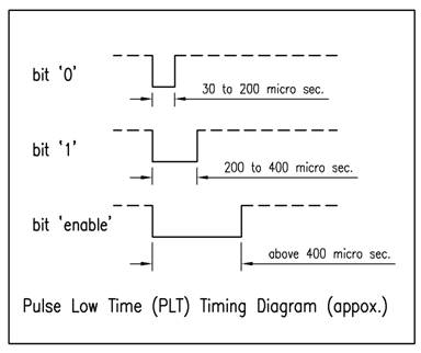
Mode 2 (PLT): When the pin 12 (PD6) of IC1 is pulled low ( connected to ground ), it is set for PLT (Pulse Low Time) mode. This mode is useful when, the USART TX of Master/Host MCU is not available or used for some other purpose. In this mode, the IC1 measures the Low time of the pulse and process for bit `0’ or bit `1’ or `enable’ bit. The type of the bit is decided by the time for which the pulse is low. The LOW TIME is to be transmitted by the Master/Host MCU through any one pin, which can be easily configured in the program. The library for the Master/Host MCU is enclosed.
In both the modes, the LCD module need not be initiated by the Master/Host MCU. Once, powered, the LCD will display the mode and/or baud rate etc., which indicates LCD module is ready to receive data from Master/Host MCU. The text to be displayed can be transmitted directly using ASCII code without worrying about RS pin of LCD. To transmit a control code (clear screen, cursor reposition etc.), byte or code ‘01’ ( one ) is to be transmitted as prefix to the control code. For example, to clear the screen of LCD, send code 0x01 then 0x01 again (where first 0x01 indicates control code follows and second 0x01 is clear screen code for LCD).
A crystal (3.6864MHz) is used for proper USART communication with Master/Host MCU without error. An independent power supply of 5VDC can be accommodated for the module using IC2 (7805 voltage regulator) or can be derived from Master/Host MCU board. Incase of independent power supply, both the boards should be connected by their ground pins.
Coding / programming:
1.Slave/ATmega8 Code : Burn / write “SinglePinLCD.hex” file to ATmega8 connected to LCD.
2.Master/Host Code : compile “SinglePinLCD_Lib.C” (using AVR studio 4 or supporting compiler) and burn/write “SinglePinLCD_Lib.hex” to any AVR MCU (as per your project).
a)Modify value of #define F_CPU as per the Clock frequency.
b)Modify #define DELAY 25 to #define DELAY 30 or 35, if the data is not displayed on LCD.
c)Port and bit can be changed for PLT mode by modifying
#define PULSE_WIDTH_REG DDRD // change DDR as you wish
#define PULSE_WIDTH_PORT PORTD // change PORT as you wish
#define PULSE_WIDTH_BIT 0b00000100 // change BIT as you wish
d)Can be tested directly on ATmega16A with 3.6864MHz crystal by writing “SinglePinLCD_Lib.hex”.
e)By following the logic of “SinglePinLCD_Lib.C”, any MCU can be programmed as Master/Host MCU.
Fuse bits for 3 to 8MHz crystal (ATmega8, ATmega16, ATmega32 etc.)
SUT0, SUT1, CKSEL3, CKSEL2, CKSEL1, CKSEL0, CKOPT are marked 1. ( means unprogrammed ).