Tank Water Level Alarm
Published by Fayaz Hassan on 23rd Jun 2019
Normally we lose water and power due to overflow of overhead tank when motor is on and do not come to know when tank is empty unless there is no water coming out of taps.
This is a simple circuit to indicate the level of water in overhead tank and make an alarm sound on extremes ( full or empty ) water level. The circuit can work on single 9V battery or 9V external DC power supply. The circuit can be housed in a suitable small plastic container.
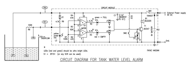
IC1 LM358 is a dual op-amp, configured to compare the input voltage from tank (TP1). The resistances, R4, R5 and R6 form voltage divider of approximately 25% and 75%. The resistances R7 and R8 form voltage divider of 50%.
Consider for situation of no water in the tank, means all points (P1,P2 and P3) are not connected / open. Hence pins 2 and 5 of IC1 goes low w.r.t. pins 3 and 6. So, the red LED glows.
Consider for the situation of half filled water in the tank, means point P1 is shorted to point P2 through the water. Hence voltage at TP1 is 50% of the power supply (i.e. TP0) and neither of the red and green LED glows.
Consider for the situation of full tank, means all points (P1, P2 and P3) are connected through water. Hence pins 2 and 5 of IC1 gets 100% voltage of the power supply (i.e. TP0). So, the green LED glows.
In any case of red or green LED glow, the signal can switch ON alarm circuit formed by transistor T1 and goli buzzer B1 (which can be directly soldered to PCB). To stop or mute the alarm, press SW2 switch, which inturn, pulls the transistor T1 low by an SCR, S1 and switches OFF the alarm. When both the LEDs are OFF, the SCR resets for next alarm.
Switch SW1 is power ON/OFF switch and the power status is indicated by an yellow LED. To reduce the battery power consumption, remove the jumper at J3.