


Description
This Multi-Functional Expansion Board is designed for use with both Raspberry Pi and Arduino. It is compatible with the Compute Module IO Board V3 from the Raspberry Pi Foundation and features a Raspberry Pi GPIO header for connecting a variety of Raspberry Pi HATs. The board also supports Arduino shields and has a 1-WIRE interface for connecting single-bus devices like DS18B20.
For I/O testing, the board features 4x keys, 4x LEDs, and 1x Buzzer. It also has an onboard USB HUB, allowing for connecting more USB devices. An IR receiver is available on the board for IR remote control. Additionally, the board has an onboard USB TO UART for serial debugging.
The sensor interface on the board allows for connecting various sensors, while the 10-bit ADC with 38KSPS and 11 channels (6 channels for Arduino interface, 5 channels for sensors) and 16-bit DAC with 2 channels provide accurate analog inputs and outputs. The onboard RTC is one of the most common and useful functions.
Compute Module IO Board Plus Features
- Compatible with the Compute Module IO Board V3 from the Raspberry Pi Foundation
- Raspberry Pi GPIO header, for connecting sorts of Raspberry Pi HATs
- Arduino connectivity, also supports Arduino shields
- 1-WIRE interface, for connecting single-bus devices like DS18B20
- 4x keys, 4x LEDs, 1x Buzzer, for I/O testing
- Onboard USB HUB, allows connecting more USB devices
- IR receiver, IR remote control is available
- Onboard USB TO UART, for serial debugging
- Sensor interface
- 10-bit ADC, 38KSPS, 11-ch (6-ch for Arduino interface, 5-ch for sensors)
- 16-bit DAC, 2-ch
- Onboard RTC, one of the most common and useful functions
-
Compute Module IO Board Plus x1
What's on the Compute Module IO Board Plus

-
Compute Module interface: for connecting Compute Module 3 OR Compute Module 3 Lite
-
Compute Module GPIO header: breakout all the Compute Module pins
-
Raspberry Pi GPIO header: for connecting Raspberry Pi HATs
-
CSI interface: camera ports, for connecting Raspberry Pi Camera
-
DSI interface: display ports, for connecting Raspberry Pi LCD
-
HDMI port
-
USB ports: for connecting USB devices
-
USB SLAVE interface: allows you to burn system image in to Compute Module 3
-
USB TO UART interface: for serial debugging
-
Arduino header: for connecting Arduino shields
-
AD/DA input/output screw terminals
-
1-WIRE interface: for connecting single-bus devices like DS18B20
-
Sensor interface
-
Power port: 5V 2.5A
-
FE1.1S: USB HUB chip
-
12MHz crystal
-
CP2102: USB TO UART converter
-
Micro SD card slot: insert a Micro SD card with pre-burnt system, to start up Compute Module 3 Lite
-
TLC1543: AD converter
-
DAC8552: 16-bit DAC, 2-ch
-
DS3231: high-precision RTC chip, I2C interface
-
RTC battery holder: supports CR1220 batteries
-
Voltage regulator: 3.3V / 2.5V / 1.8V
-
LFN0038K: IR receiver
-
Buzzer
-
Power indicator
-
ACT indicator: indicating the Micro SD card status
-
User LEDs
-
User Keys
-
BOOT selection-EN: enable the PC to access SD card/eMMC through USB SLAVE-DIS: the Compute Module will boot from SD card/eMMC
-
VGx power selection: config the I/O level
-
USB HUB enable jumper: HUB enable and USB SLAVE power selection
-
ADC/DAC configuration: config the power supply and reference voltage of ADC/DAC
-
Peripheral configuration: config the control pins of UART, user keys, user LEDs, 1-WIRE interface, IR receiver, and buzzer
-
Arduino AD selection-connect 1 and 2: Arduino A0-A5 as digital control pin-connect 2 and 3: Arduino A0-A5 as AD input
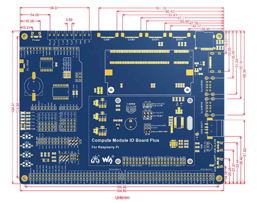
Dimensions


 BCM2837 Processor 1GB RAM 8GB Flash")

